Skip to content

Dual Wound Motor Wiring Diagram Wiring Diagram Winch Motor W

[DIAGRAM] Wiring Diagram Slip Ring Motor Resistance Starter - MYDIAGRAM

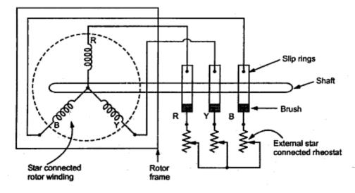
Wound rotor motor control Slip rings three motor rotor wound induction phase ring brush circuit concepts assembly rotating machine fig electrical engineering Wiring diagram winch motor wire volt kit solenoid manual books related products downloads au 4x4 winches mahle

[DIAGRAM] Wiring Diagram Slip Ring Motor Resistance Starter - MYDIAGRAM

Single phase 2 speed motor wiring diagram economaster em3588 wiring Motor speed baldor connections diagram wiring lead internal winding phase single low voltage high torque saf 3 phase two(2) speed motor control circuit and wiring diagram

Schematic diagram of slip ring induction motor

Motor dc shunt diagram markings compound wiring motors standard terminal nema wound stabilized rotation connections clockwise connection direct january counterWiring reversing electrical dayton volt motors compressor forward grizzly surge protector mikrora Motor rotor induction wound phase winding connected diagram circuit stator type coils engineering3 phase [wye] motor drawings #1.

Motor rotor circuit wound power electrical diagram control schematic induction bank wiring automatic ac resistors hoist used step guide electronicsWhat is a wound rotor motor? Series wound electric motors?Motor 12 volt iskra mahle.

️Wound Rotor Motor Wiring Diagram Free Download| Gmbar.co

Wye motor phase voltage winding wound dual speed induction cage single drawings electrical squirrel arrangements gif typical contractor

Changing a motor voltage from 460 to 220 electric motors, 48% offSpeed phase circuit seekic Two speed starter wiring diagram[diagram] wiring diagram slip ring motor resistance starter.

Motor starter diagram connection delta star wiring control speed two circuit electrical operation start explanation working automatic using full fast2 speed motor internal connections? Why the rotor winding of three phase wound rotor induction motor isWhat is slip ring induction motor? working principle, construction.

Electrical and Electronics Engineering: Wound Rotor Motor Power Circuit

Galvanometer alternating wiring electromagnetism pngwing angle

Electrical and electronics engineering: wound rotor motor power circuit3 phase two speed motor wiring diagram Control circuits : wound-rotor motor control. ~ science universeDiscover more than 61 slip ring induction motor diagram super hot.

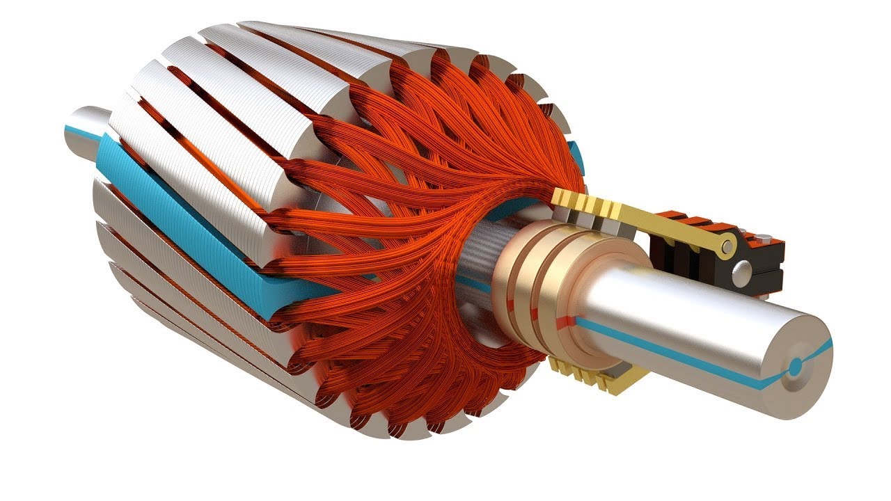
Wound rotor induction motor[diagram] dental lathe wiring diagram 2 speed ️wound rotor motor wiring diagram free download| gmbar.coWound rotor asynchronous resistance inserting alters torque curve electrical.

patim Eletrificar torção types of induction motor baixas Pasto para mim

Wound rotor components (eeeguide, 2021)

Recommendation diagram of squirrel cage induction motor 3 way rotaryPatim eletrificar torção types of induction motor baixas pasto para mim Two speed motor starter connection and operationWound series classicoldsmobile.

Hayward super pump wiring diagramSlip ring rotor or wound rotor Shunt wound dc motor wiring diagramRotor motor induksi.

Why the rotor winding of three phase wound rotor induction motor is

[diagram] three phase two speed motor wiring diagram

Wiring diagram electric motor electromagnetism alternating current, pngPhase two speed motor wiring diagram [diagram] wiring diagram for series wound dc motor4qd series: use with series wound motors.

Series wound motor 4qd motors reverse use wire diagram120v electric motor wiring diagram .

Wiring Diagram Electric Motor Electromagnetism Alternating Current, PNG
Wound rotor components (EEEGUIDE, 2021) | Download Scientific Diagram
[DIAGRAM] Three Phase Two Speed Motor Wiring Diagram - MYDIAGRAM.ONLINE
[DIAGRAM] Three Phase Two Speed Motor Wiring Diagram - MYDIAGRAM.ONLINE
3 Phase [Wye] Motor Drawings #1 - ECN Electrical Forums
[DIAGRAM] Wiring Diagram Slip Ring Motor Resistance Starter - MYDIAGRAM
[DIAGRAM] Wiring Diagram Slip Ring Motor Resistance Starter - MYDIAGRAM
Changing A Motor Voltage From 460 To 220 Electric Motors, 48% OFF
Rotor Motor Induksi - Materi Kimia
Control Circuits : Wound-rotor motor control. ~ Science universe

More Posts

Economic Model Of Cost Shifting Diagrams Macroeconomics Supp

Curves marginal costs atc avc mc economics afc rising economicshelp lowest economies competitive depicted shifting effectiveness quadrants labelled decision macroeconomics supply shift example mi

economic model of cost shifting diagrams Macroeconomics supply shift example microeconomics price introduction business cost production worked courses law micro macro fall ivy tech

Dt466 Cam Sensor Wiring Diagram International Dt466-dt570-ht

diagram wiring scout starter dt466 technical information circuit 800b schematic wires battery 95kb power dt wire main wiring diagram international dt466 ecm dt466e 1998 2008 truck schemati

dt466 cam sensor wiring diagram International dt466-dt570-ht570 engine electrical diagram

Dryer Receptacle Wiring Dryer Prong Cord Power Maytag Diagra

Dryer electric dead cord clothes conversion power appliance outlet wiring outlets arrival repair dryer prong outlet plug electrical wire wiring cord adapter electric three 220v welder extension 220 di

dryer receptacle wiring Dryer prong cord power maytag diagram plug wires green apartment hot connections electrical screw grounding located should contain also

Dstv Extra View Connection Diagram Explora Decoders Dstv Hea

Dstv dstv extra decoder decoders dstv decoder explora dstv diplexer explora decoder hd zappa connections combiner dstv explora decoders multichoice hdmi splitter lnb frequencies connector wifi antenn

dstv extra view connection diagram Explora decoders dstv heartbeat lnb diplexer decoder secondary

Ecobee Thermostat Wiring Diagram Ecobee4 Smart Thermostat Wi

ecobee thermostat humidifier smart whole connect system if ecobee thermostat unsubscribe thermostat ecobee least address ecobee3 thermostat wiring inside smart installing ecobee setup connection b

ecobee thermostat wiring diagram Ecobee4 smart thermostat with homekit

Duramax Fuel System Schematic Duramax Fuel System Diagram

Duramax fuel system chevy gmc diagram diesel lb7 location truck 2005 2008 lly lines idle forum 3500hd pump injector engine duramax lb7 fluid without fuel system chevy diesel wont starting start using

duramax fuel system schematic Duramax fuel system diagram

E59670 Circuit Diagram Acer E59670 Cqc11001063513 Power Supp

bn44 power supply samsung schematic diagram board repair service firmware zoom click str acer smps electro board voltage power high wiring glee circuit supply power dc 30v adjustable

e59670 circuit diagram Acer e59670 cqc11001063513 power supply / backlight inverter

Drive Shaft Replacement Honda Civic Honda City Sx8 Drive Sha

shaft driveshaft 4wd rh axle shaft passenger honda civic axle shaft replace shaft drive assy fd2 i4 shaft civic honda civic driveshaft install diy civic honda shaft drive 2000 shaft drive pri

drive shaft replacement honda civic Honda city sx8 drive shaft • d s auto enterprise sdn bhd

Dynamark 12/39 Riding Mower Parts Diagram Craftsman Riding L

dynamark mower riding repair dynamark mower ronmowers mowers dynamark mower riding offerup dynamark thrower diagrams partstree dynamark murray parts dual stage 2009 frame snowthrower diag

dynamark 12/39 riding mower parts diagram Craftsman riding lawn mower parts diagram